Contents
- 1.1 Design Factors
- 1.2 Pumping Plant Selection
- 1.3 Types of Pumps
- 1.4 Selecting the Distribution System
- 1.5 Sizing Distribution Lines
- 1.6 Summary
- 1.7 Pump selection
- 1.8 Related Publication:
Authors:
Conrad B. Gilbertson, USDA-ARS, Lincoln, Nebraska;
Paul E. Fischbach, University of Nebraska;
Ronald E. Hermanson, Washington State University;
Stewart W. Melvin, lowa State University;
John M. Sweeten, Texas A&M University
Reviewers:
Fred Bergsrud, University of Minnesota;
L. W. Jacobs, Michigan State University;
A. E. Peterson, University of Wisconsin;
Hugh O. Vaigneur, University of Tennessee
Manure management is an integral part of a modern swine production system. If manure is not handled in a sanitary method, diseases or other problems can occur, reducing overall production efficiency. Facilities with slurry or liquid storage require careful equipment design to adequately distribute the material to a terminal site. The terminal site is usually cropland.
Design Factors
Design factors which must be considered when planning a swine manure distribution system are:
- Climate
- soil type
- crops and their nutrient requirements (based on soil fertility test and type of crop)
- volume of manure to be applied (wet volume and dry weight basis)
- quantity of manure to be applied (based on nutrient content)
- possible salt and nutrient imbalances
- environmental and legal considerations of the application site. Once these basic design factors have been considered and preliminary calculations have been completed, the system can be planned
System design consists of four steps:
- selecting the pumping plant
- selecting a distribution system (sprinkler or surface application equipment)
- sizing the pumping plant and distribution system
- establishing a management system to optimize
Pumping Plant Selection
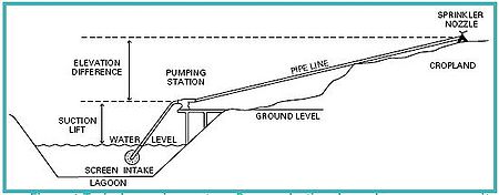
Pumping consists of lifting and pushing a liquid through a transport pipe to the application site (Fig.1). To select the proper pump, consider pump capacity (gal./min.), suction lift elevation, the elevation difference between the pump and the application site, friction loss in the transport lines, pump efficiency, required pressure, and the maximum horsepower that may be used on the power source. Pumping capacity must be determined on a site-specific basis. Determine the maximum amount of manure to be applied by estimating manure production and volume of flush or wash water used. Another pump capacity selection factor is the method of distribution, either a big gun, a lowpressure gated- pipe distribution line, or a conventional sprinkler irrigation system.
Calculate the total dynamic head the pump must work against. The total dynamic head is calculated by adding the suction lift elevation to the discharge elevation from the pump to the highest point in the system, plus friction loss in the transport pipe, plus the pressure needed at the nozzle. Lift head and elevation head are site specific. Determine the friction loss and required nozzle pressure from friction loss tables and the sprinkler manufacturer, respectively.
All pumps have a maximum theoretical suction lift height of about 34ft. However, a practical limit is 20ft. or less due to pump limitations (small pump and suction line leaks, friction loss, etc.). Many common pump problems occur with the suction side of the pump. Pumps with small leaks in the suction lift pipe or those in poor repair will not develop enough lift for satisfactory performance. Minimize the suction lift or use flooded suction where possible.
Pump speed has a direct effect on capacity, pressure head developed, cavitation, and frequency of repair. Many smaller pumps are designed to run at 3,450rpm with direct drive electric motors. Avoid these high speed pumps if they are to run continuously for long periods of time.
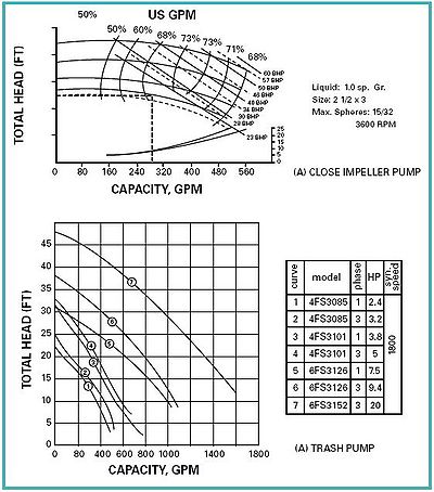
Refer to the manufacturer’s pump curve when selecting a pump. It is often referred to as a head-capacity curve. The pump curve is a performance indicator for the pump under various operating conditions and must be studied carefully (Fig. 2). The capacity in gallons per minute (gpm) and the total dynamic head in feet are the horizontal and vertical axis, respectively. Pump curves should show the pump efficiencies, the brake hp, and frequently the net positive suction head for the pump. Unfortunately, the net positive suction head and pump efficiencies are not usually given for trash type or waste handling pumps (Fig. 2) The net positive suction head is very important to the operation of pumps. Failure to match the required and available net positive suction head is a major reason cavitation occurs. Cavitation is the formation of a partial vacuum within the liquid as it passes’ rapidly through the pump. When cavitation occurs, the pump sounds as if stones are passing through the pump chamber. Your pump dealer should be contacted to prevent cavitation and resulting problems. The following example will illustrate use of a pump curve:
Example: Determine the pump flow rate in gallons per minute (gpm) if the suction lift is 10ft., the elevation difference is 25ft. uphill, the pipe friction loss is 80ft., and the discharge pressure is 30psi.
Solution: (ft.)
Suction lift 10 Discharge pressure 69
Elevation head 25 (calculate ft of discharge pressure
(Difference between highest discharge by multiplying psi x 2.31) ____
point and pump discharge) Total dynamic head 184
Friction loss 80
Types of Pumps
Two types of pumps are available, centrifugal and positive displacement pumps. The volute type centrifugal pump is the most common for handling trash waters. Water enters the pump at the center and is carried by the impeller outward into an expanding spiral. The centrifugal pump permits control of flow rates by valving down the discharge side. However, this lowers the pumping plant’s effective efficiency.
Impeller design will ultimately determine the pump characteristics. Three types of impellers are available. They are closed, semi-open, and open. A closed impeller pump develops high pressure but will not handle liquids with trash and other solids. Use it for irrigation with trash-free water, recirculating lagoon water, or pumping from a second stage lagoon directly onto cropland. Semiopen and open impellers can handle liquids with solids. A semi-open impeller has a plate on one side and is capable of handling liquids containing limited amounts of solids (less than 5%) and floating trash. The open impeller pumps have no plates attached to the impeller and can be used for high solids-content liquids with up to 15% total solids content. A chopper blade is frequently attached at the inlet to break up large chunks and fibrous material before they enter the pump chamber. Although open and semi-open impeller pumps move liquids with considerable solids content, the open impeller pumps will not develop sufficient pressure to operate a sprinkler irrigation system.
Positive displacement pump types include: gear, helical screw, lobe, piston, and diaphragm pumps. The first three pumps are characterized by a rotary motion to propel the liquid forward. Capacity normally varies with the speed of the pump; however, a limiting factor is the thickness or total solids content of the liquid. Thick, viscous fluids will not flow into the pump chamber rapidly enough to keep it at full capacity. The piston-type pump is normally placed lower than the manure to be pumped, and material is scraped into a hopper with a large throat opening. Usually, check valves are placed near the inlet and outlet of the pump chamber to control the direction of material flow. Diaphragm pumps consist of a pump casing with a flexible non-metallic diaphragm and check valves at the inlet and outlet of the chamber. As the diaphragm moves upward, the outlet check valve is closed and the intake or suction side opens allowing material to be drawn into the pump chamber. As the diaphragm moves down, the inlet check valve closes and material discharges from the chamber. Both the piston and diaphragm pumps are characterized by pulsating flows. The diaphragm pump has the ability to develop a suction lift of up to 10ft. Pulsating pumps are not desirable for irrigation but are useful as transfer pumps for more viscous and highly fibrous materials.
Power required for operating pumps should be indicated on the pump curve. If the brake hp is unavailable, it can be calculated as follows:
BHP = flow rate (gpm) x total dynamic head (ft) x specific gravity 3,960 x pump efficiency (decimal equivalent)
The flow rate in gallons per minute can be obtained from your pump curve using the total dynamic head calculated for the particular site. For all practical purposes, specific gravity of manure can be assumed equal to one. The constant 3,960 converts the units into hp. Pump efficiency may be taken as 0.5 or 0.6 (50-60% efficient) if not given on the pump curve. Table 1 illustrates the hp rating required for various pumping capacities and pump pressures. This particular table does not account for the motor or power unit efficiency. Select the motor or power unit to deliver the required horsepower continuously by using the motor nameplate for electric motors, and the continuous duty rated horsepower for internal combustion engines. Keep in mind that electric motors are approximately 80% efficient. Water and/or air-cooled engines are 25-50% efficient.
Selecting the Distribution System
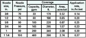
Several methods can be used to distribute liquid manure onto croplands. Sprinkler and surface application are broad categories. Sprinkler application methods include large nozzle gun, towline, and center pivot. Surface application methods include gated pipe and surface flooding systems. Large nozzle (up to 2 in. diameter) systems are normally used for distributing liquid manure with a high total solids content and some debris. The nozzles will deliver up to 600 gpm on an area of 5 acres per set.
Traveling systems may be pulled through the field or are self-propelled and may use smaller nozzles (Table 2) which cover more than 1 acre per run. The system can travel about a quarter of a mile on each run using flexible hoses to connect into the main line. Do not use water-turbinedriven traveling guns unless debris-free water is available. Towlines are more adaptable on pastures where access to equipment is easy.

A tractor must be used to move the system for each set. Towline systems have a lower power requirement than large nozzle guns because pressure requirements are less than 50psi. Towlines usually are used for relatively debris-free water such as from a secondary lagoon or runoff holding pond. Screen the pump inlet with a screen having openings so anything drawn into the pump will pass through the pump and distribution system without clogging. Special or conventional center pivots can be used to distribute liquid manure. Special center pivot systems are currently available which have automatic shut off valves on each tower. This allows use of larger nozzles (up to 1in.) to distribute high total solids content water, conventional pumps, and the advantage of covering several acres per set. Alternate sprinkler heads are automatically opened as it rotates in its circle. One or more sprinkler heads may be operated depending on pumping capacity available. The conventional center pivot may be used; however, the water must be relatively free of debris to reduce plugging of the nozzles. In areas where cropland irrigation is normally used, holding pond or lagoon effluent may be blended with irrigation water. This practice has the benefit of the crop using nutrients throughout the growing season as well as supplying water. Surface applications by gated pipe are common for conventional furrow irrigation. Care must be taken to avoid high total solids |content materials when using gated pipe systems. Heavier particles will flow through the gate but will settle out within a very short distance causing irregular flow patterns. Flow through gates can be varied from less than 5 to over 40gal./min. Slope of the land dictates the gate opening and thus the flow rate. Table 3 shows typical gate flow rates recommended for the various land slopes. Furrow irrigation is not recommended for slopes greater than 2% but has been used on land slopes up to 5%.
Surface flooding techniques may be accomplished by constructing a border or dike and flooding 3-6in. of water on that area and allowing it to infiltrate. This system works quite well for smaller livestock operations because small pumping equipment or gravity can be used to empty lagoons or holding pond effluent onto a small area adjacent to the swine.
Sizing Distribution Lines

Sizing the distribution lines is the critical part of the design once selection of the system has been completed. Main lines and laterals must be large enough to reduce friction loss, yet maintain a flow velocity of 1ft./sec. to maintain solids suspension. Avoid water hammer by maintaining flow velocity less than 6ft./sec. Water hammer can cause damage to joints and valves in the system. Table 4 illustrates friction losses anticipated in various size pipes at different flow rates. An important factor which must be considered is the total solids content of the liquids to be distributed. When total solids content is greater than 5%, the liquid becomes viscous, adding to the friction loss. Table 5 illustrates some of the total solids contents which might be expected from various liquid manure storage systems. Therefore, it is recommended that sprinkler and/or surface application techniques use dilution water to maintain the total solids content below 5%. Table 6 shows dilution factors necessary to reduce the total solids content to 5% or less.
Summary
The example problem (see page 6) illustrates the use of the tables and design factors necessary to plan and maintain a relatively problem-free system for distributing lagoon and holding pond effluent onto cropland.
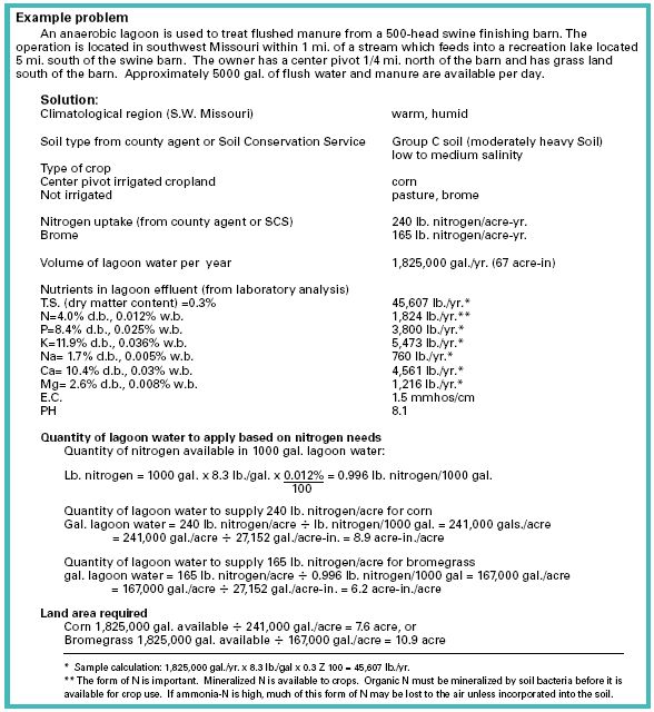
Salinity and nutrient imbalance. Because electrical conductivity (EC) is less than 4 (see laboratory analysis, salinity will not be a problem. Also, the county agent indicated all crops use K, Ca, and Mg. Na is not an essential element. However, with the warm, humid climate and low-salinity hydrologic soil group C, there should be no problem leaching the Na out. Nutrient imbalances will occur since phosphorus is applied at over 10 times that needed by the crops and potassium is applied at over 3 times that needed by the crops. Annual soil testing should be completed to avoid crop yield reductions due to nutrient imbalance or salt.
Environmental considerations. Because only 7.5-10.9 acres are necessary to dispose of the effluent, and the barn is located 5 miles north of the recreation area, no legal problem should exist if proper management is practiced.
Pump selection
The pasture is 15 acres with dimensions 1000ft. Iong by 650ft. wide. Therefore, a small traveling nozzle will be satisfactory. Table 2 indicates a 1/4in. nozzle will deliver 60gpm over 190ft. diameter at 75psi pressure, therefore:
Total dynamic head = suction lift (ft.) + elevation difference (ft.) + pressure head (ft.) + pipe friction head ft.
suction lift (assumed) …………………………. 10ft.
elevation difference (downhill from swine lagoon) ………………………………… -20ft.
pressure head (75psi x 2.31ft/psi) …….. 173ft.
friction loss
Assume 1000ft. of 2in. pipe (Table 4)
1000ft. x 5.2ft./100ft. pipe = 52ft. ______
Total dynamic head ………………………. 215ft.
The pump purchased must deliver 60gpm against a total dynamic head of 215ft. (93PSI).

Brake horsepower. Table 1 indicates 5.8hp will deliver 50gpm against 215ft. of head when the pump is 50% efficient—select a 6hp motor.

Type of pump. Table 5 indicates a closed impeller pump will operate satisfactorily for lagoon effluent with total solids content less than 1%.
Management. The nozzle will travel 1000ft. covering 190ft. diameter or 4.4 acres per set (2 sets for corn, 3 sets for bromegrass). Since phosphorus and potassium are applied at excessive rates, it is recommended that land be rotated every 4 or 5 years to reduce the chance of yield reductions. Annual soil testing should be used for monitoring nutrient levels in the soil.
Related Publication:
PIG-09-07-01 Flushing Systems for Swine Buildings
Table 1. Power requirements for selected pump capacities and heads. 1Total dynamic head = suction lift + elevation difference + pipe friction loss + nozzle pressure. Pressures (PSI) can be converted to ft of head by multiplying pressure x 2.31. 2Assumes pump efficiency = 50%.
Table 2. Capacities and coverage areas for irrigation nozzles. 1To convert rate to in./hr/ (1 nozzle only) Application rate (in./hr.) = (12.6 x flow rate (gpm)) ÷ (diameter (ft.) x diameter (ft.)
Table 3. Maximum recommendation flow rates for gated pipe.
Table 4. Estimate friction loss for liquid manure in plastic pipe. 1Assuming total solids content is less than 5%.
Table 5. Approximate total solids content of swine manure in selected storage systems. 1Moisture content (%) = 100 – total solids content (%).
Figure 1. Typical pumping system. Pump selection depends on pump capacity required, suction lift, elevation difference, pipe friction loss and pressure required.
Figure 2. Example of typical performance curves for a closed impeller pump (A) and trash-type pump (B).