Contents
- 1.1 Scraper Characteristics and Operation
- 1.2 Scraper System Components
- 1.3 Discharge Pits and Waste Removal
- 1.4 Safety Precautions
- 1.5 Emergency Operations
Originally published as PIH-105.
Authors:
Dale Vanderholm, University of Nebraska;
Stewart MeIvin, Iowa State University
Reviewers:
Lynn Cole, Mt. Blanchard, Ohio;
Mike Kula, Gettysburg, South Dakota;
Arthur W. Selders, West Virginia University;
Larry Stewart, University of Maryland
Scraper systems are a means of removing manure and other wastes from swine buildings for storage or treatment outside the building. Like other methods that allow for frequent waste removal, they reduce odor and gas production within the building from stored wastes and improve the environment. Scraper systems are adaptable to gestation, farrowing, nursery and finishing buildings and may be used either under slats or in open gutters. They can be installed in new buildings or incorporated into existing buildings. The wastes can be transported to the storage or treatment area by pumps, other mechanical means, or gravity, and full automation can usually be achieved.
Although scrapers can handle solid or semisolid wastes, the high moisture content of swine manure, along with the additional moisture from waterers, washing operations, and other sources, usually dictates that scraped swine waste from buildings be handled as a liquid. The liquid is normally stored in outdoor earthen storages or in above-ground or underground tanks. To minimize storage and transport requirements, additional dilution water is usually not added to the scraped wastes.
Scraper systems adapt well to frequent and regular loading of anaerobic digesters for biogas production because of a minimal amount of dilution water and because they are operated regularly. Frequent collection of the manure minimizes the loss of readily digestible organic materials necessary for efficient biogas production, although recent studies of scraper systems have indicated high nitrogen losses through ammonia volatilization.
Frequent collection of wastes by scrapers conserves nitrogen because it brings the wastes quickly to |storage, where relatively little nitrogen is lost. Scrapers, particularly chain link type, have been successfully used for scraping swine wastes where chopped bedding such as straw, corn cobs, peanut hulls, or similar material is used on solid floor areas and is allowed to work its way through slats or to open scrapers.
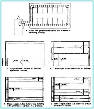
Scraper Configuration (see Fig. 1)
One drive unit can drive from 1 to 6 scrapers, depending upon the building layout and the manufacturer’s recommendations. Single scrapers are commonly used in modified open-front buildings with partially slotted floors, while multiple units are commonly used for farrowing and nursery areas, as well as in totally slotted finishing buildings. The manufacturer usually specifies the number of gutters that can be served by one drive unit, the maximum length of chain and/or cable, and the maximum area to be scraped. The configurations in Figure 1 are for illustrative purposes only. Check with your individual supplier regarding the manufacturer’s recommendations for your situation.
Scraper Characteristics and Operation
Commercial scrapers generally range from 2-12ft. wide. When scraping under slats, the required vertical clearance between the gutter floor and the underside of the slats ranges from 7-18in., depending upon the scraper type. Unless access for maintenance is required or additional depth for emergency storage is desired, additional clearance offers little advantage and adds to the construction cost. However, additional clearance, such as may occur in remodeled facilities, is not harmful. Gutters designed for scraper use are not intended for long-term manure storage. Using them for this purpose may overload the drive unit or break the cables or chains.

Construction of concrete gutters for scrapers must be carefully planned and carried out. The surface across the gutter should be uniform and level, and gutter width must not vary—to allow for good scraper contact and efficient cleaning. This is especially important for scrapers with rigid metal blades, since rough concrete, like any obstruction, can cause scrapers to shut off. Scrapers with floating or rubber-edged blades can handle slight irregularities. It is also best to select a specific scraper system before constructing a gutter so that the gutter matches the scraper width and provides adequate vertical clearance. It may be necessary to specially form the gutter to allow for installation of the scraper cable or chain hardware and the cable passages.
Level gutters are often used, but constructing gutters with a slope of 1/16 to 1/8in./ft. of gutter length toward the gutter discharge pit will provide liquid drainage and better cleaning.
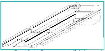
Figure 2 illustrates a commonly recommended gutter and discharge pit configuration.
Manufacturers often rate scrapers in terms of the total allowable gutter area to be scraped by each scraper unit. For example, a certain size of scraper unit may be considered adequate to handle 2,500ft2 of gutter area. The gutter area is simply the width of the scraper(s) multiplied by the distance the scraper(s) will travel in the gutter. A 10ft.-wide scraper traveling 100ft. would be scraping 1,000ft2, and two 12ft.-wide scrapers each traveling 100 ft. would be scraping 2,400ft2. If the total recommended area is exceeded, the power drive unit may be too small. Although power requirements vary, a survey of manufacturers’ literature indicates that power unit requirements usually range from 0.1-0.3hp./1,000ft2 of scraped area. The higher power requirements are usually associated with heavy-duty scrapers for open-gutter, exposed scraper assemblies rather than for underslat units. Manufacturers also usually specify the maximum gutter length for each scraper, with 200ft. being a commonly recommended value, although lengths of more than 500ft. have been used successfully for specially engineered systems. When multiple scrapers are used, a maximum total length of system cable per drive unit is usually specified.
A variety of scraper control and operating alternatives is available. Some systems are manually activated by the operator, with the system continuing to operate until switched off. Some complete a full scraping cycle and then turn off automatically. Timer controls are available that offer complete automation with great flexibility in operating schedules, although it should be recognized that completely unsupervised operations may be hazardous to livestock when uncovered scrapers are used. Selection of control options is a matter of operator preference, cost, labor availability, and size and complexity of the production facility.
Reversing-type scraper systems are normally equipped with sensor assemblies that automatically reverse the scraper when it reaches the discharge point. In addition, they often include safety components such as automatic shutoff, or they reverse when obstructions are encountered. Nonreversing types such as chain-link gutter cleaners operate in a continuous loop and usually require no special reversing switches or automatic shutoff.
The travel speed of commercially available scraper units normally ranges from 4-12ft./min. Slower speeds are usually used for heavy-duty exposed systems that could come in contact with livestock, and higher speeds are more often used with under-slat systems. The power cost for a scraper operation is low. As anexample, using the numbers cited earlier, an average power requirement of about 0.2hp./1,000ft2 of scraped area is common with scraper speeds of about 10ft./min. A system with two 5ft.-wide scrapers each scraping 100ft. of length (1,000ft2) would require 20min. for a complete cycle (scrape and return) to scrape both gutters. Each of these cycles would require 0.05kw.-hr. of electricity. At 7¢/kw.-hr., the power cost could be about 0.35¢ (one-third of a cent) for each cleaning cycle. In this example, the daily cost to continually operate equipment would be about 25¢; however, continuous operation means excessive equipment wear. Manufacturers’ recommendations, as well as operating experience, are necessary to determine the most satisfactory operating schedule.
In any scraper unit, manure can cause problems in cold climates by freezing to the gutter bottom and walls. Some manufacturers specify a higher building temperature to prevent freezing in cold weather. In extreme conditions, more frequent scraper operation aids in removing manure before it has time to freeze, but this alternative is not feasible in extremely cold temperatures. Even with warm buildings, perimeter insulation is needed in extreme climates to prevent the manure from freezing along the outside gutter walls. To scrape cold buildings in northern climates during the winter, supplemental heat may be needed in the gutter floor and walls, but the heating costs may be high.
When multiple, interconnected scraper arrangements are used in swine facilities, the scraper gutters may provide passageways that allow for undesirable air movement between sections of buildings. For example, cold air from growing-finishing sections may be drawn into warm nursery areas. This problem can be minimized with weighted, flexible curtains that restrict airflow but still allow free movement of the scraper as it moves past the curtain.
Scraper System Components
The two most common scraper systems used for swine operations are (1) cable-type scrapers using a capstan drive and (2) chain-link, continuous loop or reciprocating scrapers driven by a gear drive sprocket assembly. Cable systems are generally less expensive in terms of first cost, but chainlink scrapers can be expected to have a longer service life.
Scrapers. Most cable scrapers have a steel or steelsupported blade that scrapes on the cleaning stroke and raises by pivoting on an axis above the floor on the return stroke. Some models have divided blades that are individually hinged to improve the cleaning of slightly irregular floors. Others use a rubber or other type of flexible edge for more thorough cleaning. Blade heights vary from 5-12in., depending upon the expected frequency of cleaning and the length of the gutter. Some cable-tow scrapers use side plates to aid alignment and to reduce end spillage. Scraper units designed to operate in an open gutter without slats may use an electric shock device to keep animals clear of the unit, particularly when it passes through pen partition walls where injuries could occur. Open gutter scrapers should be supervised while operated in order to minimize the potential for livestock injury. Chainlink scrapers use both tip-up and center folding scrapers for reciprocating systems. A side mounted blade on a barn cleaner chain is sometimes used for narrow gutter systems such as those used in farrowing facilities.
Cables and Chains. Cables are usually made of stainless steel or plasticcoated galvanized steel to prevent corrosion. Common sizes range from 3/16-5/16in. diameter. Cable stretch may occur if scrapers are overloaded. Overloading may occur as a result of excessive gutter length, infrequent scraping, misalignment of the scraper unit in the gutter, worn or malfunctioning idlers, or other reasons. Since some cable failure should be expected, repair procedures should be developed before the scraper is installed. Provisions for restringing cables through long shallow gutters should be considered. One suggestion is to stretch a looped, thin nylon rope twice the gutter length under the slatted floor but clear of the scraper. The rope will ease the task of threading a cable under the slatted floor. Chain scrapers use heavy-duty chains made of flatlength and forged-eye links, with tensile strengths ranging up to 48,000lb. for heavy duty applications. Chains may be run in a channel in the center of the gutter or on the surface, depending upon the manufacturer.
Drive Units. Cable-system drive units consist of one or two electric motor powered drum assemblies and a speed reduction mechanism. Belt- and gear-drive mechanisms reduce speed and multiply torque for powering the scraper assembly. Some means of controlling cable tension is required to obtain proper tension in the cables. Power units commonly range from 1/4-1/2hp., depending upon the maximum recommended scraping area, speed, and length of run of the scraper assembly. The power required is a function of the force required to pull the scraper and the desired speed. Large scraping surfaces need drive mechanisms that can develop a high torsion load without undergoing undue wear and failure. Chain-link drives normally have a gear drive.
Because of extremely corrosive conditions in pit areas, it is desirable to keep drive units up and out of these areas whenever possible. Drive units located near the scraper discharge should not be located where damage can occur if the receiving pit discharge system fails.
Corner Wheels. Corner wheels are used to change the direction of the cable or chain that is pulling the scraper assembly. The wheels may be mounted either on the floor or on the wall. Wheels may be made of cast iron or other materials such as phenolic resins. Although various types of bearings are available, most corner wheels still require periodic lubrication. Wheels should be able to withstand tension from the cable or chain without undue wear or creating excessive wear on the cable or chains. Since the wheels must be lubricated regularly, they should be easily accessible and not located where pigs, slat sections, and manure accumulations must be moved before they can be reached.
Discharge Pits and Waste Removal
The receiving pit for scraper discharge should have a vertical or steeply sloping side to allow the waste to move freely from the scraper. The pit size and shape depend upon the frequency of removal and the method used to remove waste for storage or treatment. Transport alternatives include gravity flow, cross scrapers, augers, centrifugal pumps, piston pumps, and pneumatic conveyors.
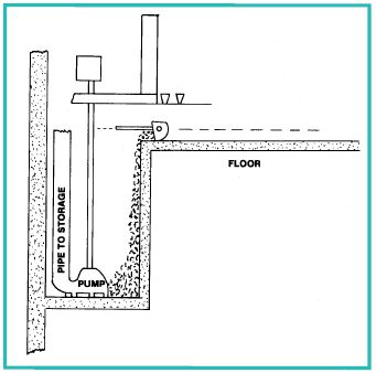
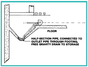
When storage units are at a lower elevation than the receiving pit, gravity discharge is the most economical method of moving wastes to storage. Gravity discharge pipes should have diameters of 6in. or more, should be of clay or plastic, and should have a minimum slope of 1% for 6in. diameter pipes and 0.6% for 8in. or larger diameter pipes. Pipe in outdoor areas must be buried deep enough to escape freezing. The discharge pipe may be left open to allow for continuous drainage from the pit; but to minimize freezing and clogging problems caused by settling, the recommended configuration provides sump storage for up to 24hr. and has a manually operated plug at the entrance to the discharge pipe. This plug is pulled when the pit is nearly full, discharging the contents rapidly, removing settled solids from the pit and preventing settling in the discharge pipe. The plug also eliminates gases and odors being pulled back into the building from a covered storage unit. Examples of receiving pits are shown in Figures 3, 4, and 5.
Pumps for emptying pits receiving scraped swine wastes should be capable of handling moderate levels of solids up to 8%. Heavy-duty submersible sewage pumps and chopper-type manure pumps with open impellers and adequate internal clearances to pass at least 1in. diameter solid pieces have proven satisfactory. Helical rotor pumps, piston pumps, and pneumatic conveyors can also be used, with the latter two capable of handling wastes with higher solids contents, such as occur with manure and bedding mixtures. Highpressure centrifugal pumps are not normally used for emptying pits. Where outside above-ground storage tanks are used, pit pumps may be used to fill and agitate the storage tank and also to fill tank wagons when stored manure is discharged by gravity flow back into the receiving pit. Pit pumps are typically used only to fill outdoor storage, and a second high-capacity pump is used to agitate storage and to fill tank wagons. Points to consider when selecting an outdoor storage plan are cost, topography and other site characteristics, and operator preference. Above-ground storage tanks of concrete and coated steel offer a compact, attractive storage alternative. Underground pits of cast, reinforced concrete have similar operating characteristics but may be safety hazards unless fenced, covered or otherwise protected from human or animal entry. Lower-cost alternatives include open earthen storages and earthen storages with plastic liners and covers. Safety considerations also apply to these alternatives.
A common problem in all types of storage is the accumulation of settled solids in a bottom sludge layer, which takes up storage capacity and is very difficult to remove. The most effective way to prevent this problem is to thoroughly agitate the stored manure whenever the storage is emptied. Repeated removal of liquid from the storage without adequate agitation will nearly always result in accumulation of dense, difficult- to-remove sludge.
Safety Precautions
Cable and chain drives, pulleys, and idlers can be hazardous if they are not shielded or otherwise protected from access. Sealed electrical components should be used in the corrosive atmosphere associated with manure gutters and should be inspected frequently to determine whether any potential safety hazards are developing. Automated systems should be disconnected prior to maintenance to prevent injury caused by unexpected scraper operation.
Operators should use similar precautions with storage units associated with scraper units as with any other liquid manure systems. Deaths from asphyxiation or hydrogen sulfide exposure have resulted from operators entering storage tanks or from improperly ventilated, covered storage systems. Read and follow guidelines in PIH- 03-06-02, Safety in Swine Production Systems.
Emergency Operations
If power is interrupted, standby power might be needed to continue scraping and to prevent excessive manure from accumulating in gutters. If excess accumulation does occur, care must be taken to prevent scraper overloading and possible chain or cable breakage when the scraper is started. Adding water may help move manure accumulations.
Figure 1. Alternative Scraper Layouts.
Figure 2. Double-alley scraper system with single power unit.
Figure 3. Discharge pit with plug and gravity drain
Figure 4. Discharge pit with pump and for shortterm storage.
Figure 5. Discharge pit with free gravity drain (plug as in Fig. 3, rather than free drain recommended for moist situations).