Contents
- 1.1 Scraper Systems
- 1.2 Scraper System Components
- 1.3 Gravity Drain Gutter Systems
- 1.4 Manure Transfer Systems
- 1.5 Safety
- 1.6 References
Originally published as PIH-95.
Authors:
Don D. Jones, Purdue University
Reviewers:
Eldridge Collins, Jr., Virginia Tech;
Doug Hamilton, Oklahoma State University;
Jay Harmon, Iowa State University;
Larry Jacobson, University of Minnesota
Research has shown and field experience has verified that corrosive and odorous gas production increases with storage time and storage temperature. Manure can be removed from a swine barn by: (1) manual or mechanical scraping, (2) gravity draining, (3) flushing with dump tanks, siphons or pumping systems with automatic or manually controlled valves, or (4) continuous flushing. Flushing often requires large amounts of water (over 50 gal./ft. of gutter width per day). Flushing or recirculation from treatment lagoons is not practical in all areas because of odor nuisance potential from associated lagoons and/or soil types at the lagoon construction site that do not seal adequately. This fact sheet will discuss scrapers and gravity drain systems. The other options are covered in PIH-63, “Recirculation Systems for Manure Removal”.
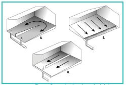
Scraper Systems

Scraper systems are a means of removing manure and other wastes from swine buildings for storage or treatment outside the building (Figure 1). Frequent collection of wastes by scrapers conserves nitrogen because it brings the wastes quickly to storage, where relatively little nitrogen is lost. Scraper systems are not recommended for use in open gutters where the scrapers would be in contact with pigs.
One drive unit can drive from 1 to 6 scrapers, depending upon the building layout and the manufacturer’s recommendations. Single scrapers are commonly used in modified openfront buildings with partially slotted floors, while multiple units are commonly used for farrowing and nursery areas, as well as in totally slotted finishing buildings. The manufacturer usually specifies the number of gutters that can be served by one drive unit, the maximum length of chain and/or cable, and the maximum area to be scraped.
Scraper Characteristics and Operation
Commercial scrapers generally range from 1-1/2 to 12ft. wide. The required vertical clearance between the gutter floor and the underside of the slats ranges from 7-18in., depending upon the scraper type. Unless access for maintenance is required, additional clearance offers little advantage and adds to the construction cost.
Concrete gutters for scrapers must be carefully designed. The surface across the gutter should be uniform and level, and gutter width must not vary—to allow for good scraper contact and efficient cleaning.
Scrapers with floating or rubberedged blades can handle slight irregularities. Select a specific scraper type of system before constructing a gutter so that the gutter matches the scraper width and provides adequate vertical clearance. Level gutters are often used, but constructing gutters with a slope of 1/16in./ft of gutter length toward the gutter discharge pit will help with liquid drainage.
Manufacturers often rate scrapers in terms of the total allowable gutter area to be scraped by each scraper unit. For example, a certain size of scraper unit may be considered adequate to handle 2,500ft2 of gutter area. The gutter area is simply the width of the scraper(s) multiplied by the distance the scraper(s) will travel in the gutter. A 10ft.-wide scraper traveling 100ft. would be scraping 1,000ft2, and two 12ft.-wide scrapers each traveling 100ft. would be scraping 2,400ft2. If the total recommended area is exceeded, the power drive unit may be too small. Manufacturers also usually specify the maximum gutter length for each scraper, with 200ft. being a common limit, although lengths of more than 500ft. have been used successfully with specially engineered systems. When multiple scrapers are used, a maximum total length of system cable per drive unit is usually specified.
Some systems are manually activated by the operator, with the system continuing to operate until switched off. Some complete a full scraping cycle and then turn off automatically. Timer controls also are available that offer complete automation with great flexibility in operating schedules.
Reversing-type scraper systems are normally equipped with sensor assemblies that automatically reverse the scraper when it reaches the discharge point. Nonreversing types such as chain-link gutter cleaners operate in a continuous loop and usually require no special reversing switches or automatic shutoff.
The travel speed of commercially available scraper units normally ranges from 4-12ft./min.
The power cost for a scraper operation is low. An average power requirement of about 0.2hp./1,000ft2 of scraped area is common with scraper speeds of about 10ft./min. A system with two 5ft.-wide scrapers each scraping 100ft. of length (1,000ft2) would require 20min. for a complete cycle (scrape and return) to scrape both gutters. Each of these cycles would require 0.05kw.-hr. of electricity. At 7¢/kw.-hr., the power cost could be about.
Perimeter insulation is needed in extreme climates to prevent the manure from freezing if the gutters run along the outside building walls. When multiple, interconnected scraper arrangements are used in swine facilities, the scraper gutters may provide passageways that allow for undesirable air movement between sections of buildings. For example, cold air from growingfinishing sections may be drawn into warm nursery areas. This is a biosecurity problem that can be prevented by proper building design.
Scraper System Components
The two most common scraper systems used for swine operations are (1) cable-type scrapers using a capstan drive and (2) chain-link, continuous loop or reciprocating scrapers driven by a gear-drive sprocket assembly. Cable systems are generally less expensive in terms of first cost, but chain-link scrapers can be expected to have a longer service life.
Scrapers. Most cable scrapers have a steel or steel-supported blade that scrapes on the cleaning stroke and raises by pivoting on an axis above the floor on the return stroke. Some models have divided blades that are individually hinged to improve the cleaning of slightly irregular floors. Others use a rubber or other type of flexible edge for more thorough cleaning. Blade heights vary from 5-12in. Some cable-tow scrapers use side plates to aid alignment and to reduce end spillage. Chain-link scrapers use both tip-up and center folding scrapers for reciprocating systems. A side-mounted blade on a barn cleaner chain is sometimes used for narrow gutter systems such as those used in remodeled farrowing facilities.
Cables and Chains. Cables are usually made of stainless steel or plastic-coated galvanized steel to prevent corrosion. Common sizes range from 3/16 to 5/16in. in diameter. Because some cable failure should be expected, repair procedures should be developed before the scraper is installed. Provisions for restringing cables through long shallow gutters should be considered. One suggestion has been to stretch a looped, thin nylon rope twice the gutter length under the slatted floor but clear of the scraper. The rope will ease the task of threading a cable under the slatted floor.
Drive Units. Cable-system drive units consist of one or two electric motor powered drum assemblies and a speed reduction mechanism. Belt- and gear-drive mechanisms reduce speed and multiply torque for powering the scraper assembly. Some means of controlling cable tension is required to obtain proper tension in the cables. Although power requirements vary, a survey of manufacturers’ literature indicates that power unit requirements usually range from 0.1hp to 0.3hp/1,000ft2 of scraped area. The power required is a function of the force required to pull the scraper. Large scraping surfaces need drive mechanisms that can develop a high torsion load without undergoing undue wear and failure. Chain-link drives normally have a gear drive. Because of corrosive conditions in gutter areas, it is desirable to keep drive units up and out of these areas whenever possible.
Corner Wheels. Corner wheels are used to change the direction of the cable or chain that is pulling the scraper assembly The wheels may be mounted either on the floor or on the wall. Wheels may be made of cast iron or other materials such as phenolic resins. Although various types of bearings are available, most corner wheels still require periodic lubrication. Since the wheels must be lubricated regularly, they should be easily accessible.
Safety Precautions. Cable and chain drives, pulleys, and idlers can be hazardous if they are not shielded or otherwise protected from access. Sealed electrical components should be used in the corrosive atmosphere associated with manure gutters and should be inspected frequently to determine whether any potential safety hazards are developing. Automated systems should be disconnected prior to maintenance to prevent injury caused by unexpected scraper operation. Operators should use similar precautions with storage units associated with scraper units as with any other liquid manure systems. Deaths from asphyxiation or hydrogen sulfide exposure have resulted from operators entering storage tanks or from improperly ventilated, covered storage systems. Read and follow guidelines in PIH-03-06-02, “Safety in Swine Production Systems.”
Gravity Drain Gutter Systems
A gravity drain gutter is a manure handling system that has no mechanical parts and requires little or no dilution water to remove manure from a building. The liquids and solids are held in a gutter for a few days, or until sufficient depth of manure is available for draining manure out through removable plugs. The drainage interval may vary from one day in narrow gutters for larger pigs to a month in wide and deep gutters. Recirculation systems are a modification of gravity drain gutters (see PIH-09-07-01).
Design of Gravity Drain Gutters
Gutter shapes vary considerably (Figure 2), with a trend toward the flat bottom hairpin gutter.
An accumulated manure depth of 12in. often is adequate to allow the manure to flow toward the outlet when the plug is pulled. More depth is required in larger gutters.
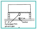
In the reversing hairpin gutter, liquid depth can vary from 16-36in., but the most common depth is 24in. The width varies from 2-12ft. Farrowing and nursery gutters sometimes have pit ventilation ducts above the divider wall or a central plenum under the service alley (see PIH-60, “Mechanical Ventilation of Swine Buildings”).
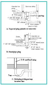
The drainage outlet from the gutter must be equipped with an easy-to-remove water-tight plug. Three types are shown in Figure 3. Fit the plugs into a 90-degree elbow or tee (regular or saddle type). It is better to have an overflow and gas trap as part of the plug, in case a waterer leaks or breaks. The ones shown have a built-in gas trap to prevent back drafting of pit gases when the barn has negative pressure ventilation. Locate the plug outside the pen or crate or otherwise protect from pig contact. For a multiple room facility, consider locating the plugs in a common alley outside the rooms (Figure 4).
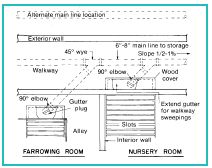
The access to the drain must seal tightly to keep air from entering the room and interfering with ventilation system performance. Placing the main sewer outside the perimeter of the barn makes maintenance simpler. For conventionallysized rooms that are drained individually, a minimum of a 6in. diameter main sewer pipe is needed (8in. is recommended). If the barn has 4 or more rooms, and all gutter plugs will be pulled in a short interval, use an 8in. or larger sewer pipe. For very large rooms, consult a qualified professional engineer. A perspective view of the reversing hairpin gutters with two plugs is shown in Figure 5. Both drains should be at least 8 in. in diameter.

Floor Cross Sections of Gravity Drain Gutters
Three cross-sections of gravity drain gutters are shown in Figures 6A through 6C. The example in Figure 6A utilizes the reversing hairpin gutter under the entire pen. Gutter depth can vary from 16-24in. The alleys can be raised higher than the gutter bottom to reduce leakage under the wall into the alley or a keyway (1x1in.) can be used to tie the floor and wall together for a better seal. The walls can be 6in. concrete block or 4in. of poured concrete with reinforcing. These work best in partially slatted pens. Maximum gutter width is 12ft. This may require a short divider wall to direct the flow during draining unless the gutters are recharged with extra water from a two-stage lagoon (recirculation system). The recommended maximum length is 100ft. (200ft. of draining length). High moisture cracked corn feed can cause these gutters to drain poorly. Wet feeders and gravity gutters do not work well together due to the reduced waterer spillage and may require additional dilution water. Grower-finisher gutters fill faster than farrowing-nursery gutters and can be drained more frequently so pit ventilation is not as important.
Reversing hairpin gutters extending under multiple rooms can be sealed tighter between rooms than buildings with scraper systems. This is especially important in mechanically ventilated buildings. A pressure treated hinged door that drops down below the manure surface can minimize air exchange between rooms.
The example in Figure 6B (used for farrowing or nursery) utilizes a formed concrete or plastic pan under the slotted floor. A 3-6in. clearance is needed between the flooring and the start of the front slope for access to wash down feed and manure solids. An alternative of washing the sloped floor directly through the slotted flooring may splash too much water on the pigs unless they are first moved out. The cross-section shown as Figure 6C is a simple rectangular collection gutter. There would typically be no cross slope and no more than 1in. in 20ft. to a drain to outside storage. Adding one inch or more of water to the gutter after draining facilitates better drainage of the gutter next time, particularly if it is greater than 40ft. long. “Wet” feeders where nipple waterers are over the feed trough minimize waterer spillage. The manure may be too thick to flow unless extra water is added.
Management of the Gravity Gutter
To minimize gas production, a gravity drain gutter should be sized to fill and be emptied within four days. If manure remains in the gutter for more than one week, pit ventilation should be used.
Draining Gutter. It is important to have the gutter filled to at least an 8-12in. depth before emptying the contents in order to scour solids from the upper end. When replacing the plug or gate, wiggle it in the slot or seat to be sure the outlet is tightly closed. With adequate airflow in larger pig buildings (grower and finisher) odor should be minimal especially with partial slat building where insulated sidewall ventilation doors or insulated curtains are used. The reversing action in hairpin units of pulling alternate plugs minimizes solids buildup. If the producer wants to completely clean the gutter of manure, water can be added at the end opposite the plugs. There should not be a lip at the plug so that the pit can drain completely at clean up.
Manure Transfer Systems
If possible, design both scraper and gravity drain systems so that manure flows to the storage by gravity. Drain pipes for the plugs should be at least 6in. for farrowing and nursery buildings to prevent plugging, with the exception being the reversing hairpin gutters which should have a minimum 8in. diameter pipes. Eight-inch drainpipes are needed for finishing barns and gestation/breeding buildings, and very large building gutters should have the drain sized by a qualified engineer. Slope the pipe at least 1% (1/8in./ft.) to 2% (1/4in./ft.) to achieve good cleaning velocities. The maximum distance between cleanouts in the drainpipe should not exceed 300ft. The storage inlet should be at least 3ft. off the bottom since solids tend to settle out at the point where the manure enters the storage. To obtain sufficient slope for gravity transfer of manure, it may be necessary to construct the barn floor on extra fill; otherwise, storage capacity is lost by not using all of the available height. Another alternative is a collection sump with a pump to lift the manure into the storage (for sump information, see PIH 09-07-04, “Pumping Liquid Manure from Swine Lagoons and Holding Ponds”). Use a pump large enough to handle 1-in. diameter solids.
Manure Storage
Manure can be stored in a properly sealed concrete or glassclad steel tank, earthen structure, or an earthen treatment lagoon. Check state regulations for construction standards and minimum storage criteria and odor stipulations (180 days or more is required in some states).
Caution should be exercised when draining or pumping into a storage under an occupied building since this can agitate that manure and release gases. Some pit gases are poisonous. A negative ventilation system is needed in the pit to reduce gasses released into the building or room from a storage area if an open pit without a gas trap is used.
Safety
Do not enter collection sumps, manure storages, or hauling tanks, unless they have been and are being well-ventilated. Also, do not enter these structures without a self-contained breathing apparatus or an airline. In addition, a body harness with a lifeline should be used, with two people standing by who are capable of lifting a person from the storage.
References
Meyer, D. J. and J. C. Converse. Gas Production vs. Storage Time on Swine Nursery Manure. ASAE Paper 81-4512.
Avery, G. L., G. E. Merva, J. B. Gerrish. Hydrogen Sulfide Production in Swine Confinement Units. Trans. ASAE 1975. p. 149-151.
Figure 1. Alternative Scraper Layouts.
Figure 2. Gravity drain gutter.
Figure 3. Alternative watertight plugs for gutter outlets
Figure 4. Plan view of main Sewer line connection to gutter plugs.
Figure 5. Perspective view of reversing hairpin gutter.
Figure 6. Perspective view of reversing hairpin gutter.